- tyler@shipplate.com
- +86 15603721115
Larssen sheet piles are modeled as elasto-plastic beams based on an uncoupled elasto-plastic spring (representing the soil). L600, L600K, and L601 are intended to provide guidance for the safe design and economic construction of sheet pile retaining walls and flood walls. When the anchored sheet piles are embedded to a small depth and the pile tip rotates, they are said to have free soil support. L716 and L720 do not prohibit the use of alternative analysis methods, as long as they maintain the same safety and economy as the structures designed using the methods described herein. Therefore, there are no inflection points in the piles.
L703 assumes that the base of the pile is relatively free to move, so passive resistance is applied only on one face. Stiffness. Elastic bending stiffness and normal stiffness about the beam axis can be uniform or variable. Libraries for L602, L603, and L603K can be used to quickly select standard and user-defined sheet pile profiles. References L606 and L607 relevant to this manual are listed in Appendix A. Appendix A also contains additional references related to the subject matter of this manual.
The pile foundation is assumed to be relatively fixed, with a point of deflection above the pile toe. Normal forces can be introduced by the user, and L603 10/10, L604, and L605 will calculate the additional bending moments and displacements caused by the input normal forces. Passive resistance acts on both sides of the pile foundation (similar to a cantilever pile). Lateral pressure increases linearly with pile depth. There is no pile-wall friction. Various computer programs are available to assist in applying some of the analytical functions described in this manual.
A dedicated Combination Wall Wizard calculates relevant values for walls composed of a combination of sheet piles and piles. This manual is intended for all Headquarters U.S. Army Corps of Engineers (HQUSACE) divisions, major subordinate commands, regions, laboratories, and field operations activities (FOAs) responsible for civil works. When L602 and L603 sheet piles are anchored to a greater depth and the pile tip is fixed to prevent rotation, the sheet piles are said to be free-soil supported. This causes a change in the curvature of the pile, resulting in an inflection point. L606 and L607 determine these yield values based on well-established sliding surface theories such as Culmann, Kötter, or Müller-Breslau. Elastoplasticity is employed. L604 and L605 accommodate soil stiffness in both the initial loaded state and the unloading/reloading state. Types of anchored sheet pile walls include: 1. Free soil-supported piles and 2. Pinned soil-supported piles. Geometric nonlinearity is present. Compressive normal forces introduce additional bending. D-SHEET PILING uses Jáky's formula to calculate the lateral stress ratio, K0, and derive the initial horizontal stress from the approximate initial vertical stress. Soil-structure interaction analysis of cantilever or anchored walls is performed (Dawkins 1992). L600, L600K, and L601, based on the Boussinesq stress distribution theory, calculate additional stresses caused by overloads or non-horizontal ground. For free soil-supported piles, the lateral pressure increases linearly with depth. Wall friction is negligible. L703, L716, and L720 utilize multiple linear relationships between horizontal stress and displacement, with different values for active and passive yielding. Initial stress.
Sheet pile construction employs a variety of classical design and analysis techniques to determine the required penetration depth and/or safety factor, including the application of the Rowe moment reduction method to the anchor wall (CORPS Project X0031). L603K and L603 10/10 anchors feature arbitrary orientation, elastic normal stiffness, zero pressure conditions, and limited bearing capacity due to yielding or soil resistance (Figure 1.2). Anchor preload is optional.
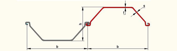
Specifications
Section | Dimensions | Mass | Moment of inertia | Modulus of section | ||||
Width | Height | Thickness | Per pile | Wall | ||||
b | h | t | s | |||||
mm | mm | mm | mm | kg/m | kg/m2 | cm4/m | cm3/m | |
L600 | 600 | 150 | 9.5 | 9.5 | 56.4 | 94 | 3825 | 510 |
L600K | 600 | 150 | 10 | 10 | 59.4 | 99 | 4050 | 540 |
L601 | 600 | 310 | 7.5 | 6.4 | 46.8 | 78 | 11520 | 745 |
L602 | 600 | 310 | 8.2 | 8 | 53.4 | 89 | 12870 | 830 |
L603 | 600 | 310 | 9.7 | 8.2 | 64.8 | 108 | 18600 | 1200 |
L603K | 600 | 310 | 10 | 9 | 68.1 | 113.5 | 19220 | 1240 |
L603 10/10 | 600 | 310 | 10 | 10 | 69.6 | 116 | 19530 | 1260 |
L604 | 600 | 380 | 10 | 9 | 73.8 | 123 | 30400 | 1600 |
L605 | 600 | 420 | 13 | 9.2 | 85.5 | 142.5 | 43890 | 2090 |
L606 | 600 | 435 | 14.4 | 9.2 | 94.2 | 157 | 54375 | 2500 |
L607 | 600 | 452 | 19 | 10.6 | 114 | 190 | 72320 | 3200 |
L703 | 700 | 400 | 9.5 | 8 | 67.5 | 96.4 | 24200 | 1210 |
L716 | 700 | 440 | 10.2 | 9.5 | 79.9 | 114.2 | 35200 | 1600 |
L720 | 750 | 450 | 12 | 10 | 96.4 | 128.5 | 45000 | 2000 |